Smart Switch NodeMCU – Works with Google Home & Amazon Alexa

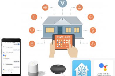
Google assistant is AI (Artificial Intelligence) based voice command service. Using voice, we can interact with google assistant and it can search on the internet, schedule events, set alarms, control appliances, etc. This service is available on smartphones and Google Home devices.

We can control smart home devices including lights, switches, fans, thermostats and many more devices using our Google Assistant.

A lot of commercial devices already exist in the market for such application but,. Here i have explained how to build your own smart switch using NodeMCU (ESP8266) development board and few other electrical components.

Components used;

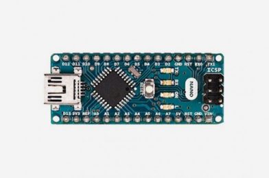
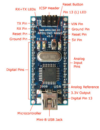
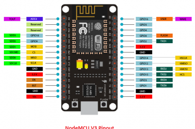
  • NodeMCU (ESP8266) Development Board.
  • Solid State Relay Module.
  • 6V Power Supply Module.
  • Connection Wires.

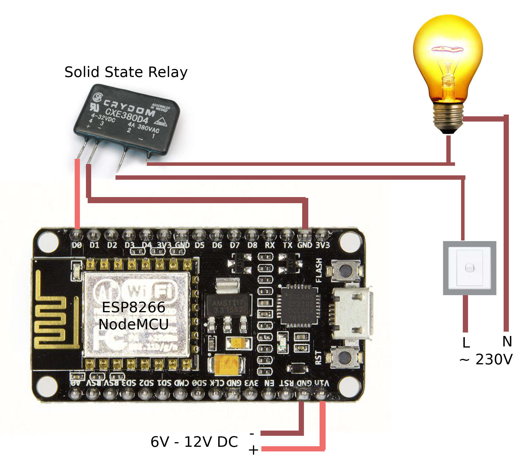
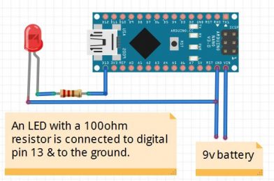
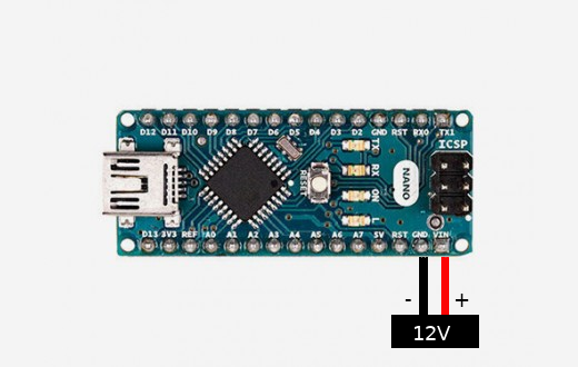
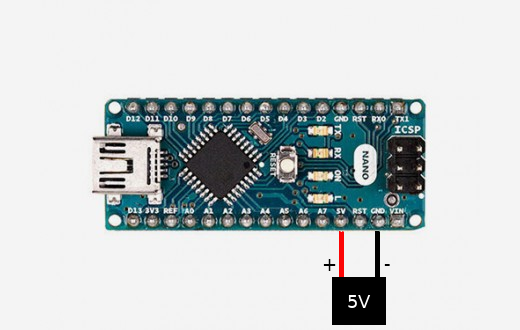
Above figure explained very simply about the circuit diagram. Be aware when you connecting this to the main power. If you don’t have enough knowledge about connecting this to the main power system, please get some help from a experienced  technician.

Before you connect using above explained diagram, you must programme the NodeMCU development board. Otherwise you cannot control it using Google Smart Home Assistant with voice commands.

In above diagram, i used D0 – Digital pin to control the input signal connected to the Solid State Relay module. When we want to switch on the light, we need to set it to high voltage state (5V), and when we want to switch of the light, we need to set it to low voltage state (0V).

You can find the source code which needs to be uploaded to the NodeMCU development borad using Arduino IDE here. https://github.com/lahirutm/WebserviceLK-IoT/blob/master/arduino_examples/state_save_light_example.ino

Once you programmed your NodeMCU, you must link it with Google Home Assistant to control using voice commands. Please follow the steps explained here.  https://iot.webservice.lk/

Enjoy using your own smart home devices…

Blinking LED With Arduino Nano

Things you need: Arduino Nano, 3V LED, 100 Ohm Resistor

To power up the Arduino Nano board, you can use USB cable or an external power supply (7V ~ 12V DC) by connecting positive pin to VIN and and negative to the ground. Please see my previous post about powering up Arduino Nano here: https://blogs.webservice.lk/2020/03/17/powering-up-arduino-nano/

To connect LED, use LED’s positive end to the one end of resistor and other end to Arduino Nano’s digital pin 13 & negative end to the  one of Arduino Nano’s ground pin. Please see the picture above.

Now circuit making part is done, Let’s do the programing.

int ledPin =  13;// the number of the LED pin

void setup() {
  // set the digital pin as output:
  pinMode(ledPin, OUTPUT);
}

void loop() {
  digitalWrite(ledPin, HIGH);   // turn the LED on (HIGH is the voltage level)
  delay(1000);                       // wait for a second
  digitalWrite(ledPin, LOW);    // turn the LED off by making the voltage LOW
  delay(1000);
}

Upload above sketch to the Arduino Nano and see the result. Led will blink with the 1 second delay.

Powering Up Arduino Nano

The Arduino Nano is a small, complete, and breadboard-friendly board based on the ATmega328P (Arduino Nano 3.x). It has more or less the same functionality of the Arduino Duemilanove, but in a different package. It lacks only a DC power jack, and works with a Mini-B USB cable instead of a standard one.

The Arduino Nano can be powered via the Mini-B USB Jack (5V) connection. 


The Arduino Nano accepts the 7V to 12V input power from the Vin pin (pin30).


If you want to supply regulated power, then a 5V regulated adapter needs to feed the +5V pin (pin27) instead.


The power source is automatically selected to the highest voltage source if you input multiple power inputs.

NodeMCU ESP8266

NodeMCU is a low-cost open source IoT platform. It initially included firmware which runs on the ESP8266 Wi-Fi SoC from Espressif Systems, and hardware which was based on the ESP-12 module. Later, support for the ESP32 32-bit MCU was added.

NodeMCU Development board is featured with wifi capability, analog pin, digital pins and serial communication protocols.

NodeMCU with Arduino IDE

We can develop applications on NodeMCU using Arduino development environment. This makes easy for Arduino developers than learning new language and IDE for NodeMCU.

When we write and compile code using Arduino IDE, ESP8266 tool chain in background creates binary firmware file of the code. And when we upload it to the NodeMCU, it will flash whole NodeMCU firmware with newly generated binary firmware code.


Arduino Nano

The Arduino Nano is one of the smallest and yet most exciting breadboard-friendly boards available on the market today. It’s become exceptionally popular with beginner programmers thanks to its excellent functionality and the sheer variation of potential applications. Based on the ATmega328P, this tool is fantastic for those who wish to improve their programming skills and create some interesting and unusual projects. While the item does not come with a DC power pack, it benefits from a mini-USB cable for power, and that means you can use it with any PC or laptop device.