Introduction
Sure, here’s the continuation of the article:
Introduction
LiFePo4 Batteries have gained significant popularity in recent years due to their exceptional performance and reliability. In this comprehensive blog, we will delve into the various aspects of LiFePo4 batteries, including their overview, advantages, disadvantages, applications, charging and discharging characteristics, comparison with other battery technologies, safety considerations, and maintenance and care. So, let’s get started!
Overview of LiFePo4 Batteries
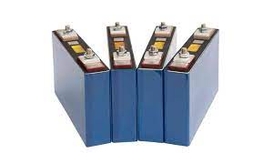
LiFePo4, which stands for Lithium Iron Phosphate, is a type of rechargeable battery that belongs to the lithium-ion family. These batteries are known for their high energy density, long cycle life, and impressive thermal stability. LiFePo4 batteries have become a preferred choice for various applications, ranging from electric vehicles and renewable energy storage to portable devices and marine applications.
Advantages of LiFePo4 Batteries
One of the key advantages of LiFePo4 batteries is their enhanced safety compared to other lithium-ion batteries. They have a lower risk of thermal runaway, making them less prone to overheating or catching fire. Additionally, LiFePo4 batteries offer a longer lifespan, with a typical cycle life of 2000 to 5000 cycles, depending on the depth of discharge.
Disadvantages of LiFePo4 Batteries
While LiFePo4 batteries have many advantages, it’s important to consider their limitations as well. One of the main disadvantages is their comparatively lower energy density when compared to other lithium-ion battery chemistries. This means that LiFePo4 batteries may have a larger physical size and weight for a given energy capacity. However, advancements in technology are continuously improving the energy density of LiFePo4 batteries.
Applications of LiFePo4 Batteries
LiFePo4 batteries find applications in a wide range of industries. They are extensively used in electric vehicles (EVs) due to their high power density, fast charging capabilities, and long cycle life. These batteries are also utilized in renewable energy systems, such as solar and wind power storage, as they provide reliable and efficient energy storage solutions. Additionally, LiFePo4 batteries are commonly used in portable devices, like laptops and smartphones, as well as in marine applications for powering boats and yachts.
Charging and Discharging Characteristics
LiFePo4 batteries have unique charging and discharging characteristics. They can be charged at higher currents, allowing for faster charging times. Moreover, LiFePo4 batteries exhibit a relatively flat discharge curve, providing a stable voltage output throughout most of their discharge cycle. This makes them ideal for applications where a consistent power supply is required.
Comparison with Other Battery Technologies
When comparing LiFePo4 batteries with other battery technologies, such as lithium cobalt oxide (LiCoO2) or lithium manganese oxide (LiMn2O4), several factors come into play. LiFePo4 batteries offer better thermal stability, improved safety, and a longer lifespan. However, they have a lower energy density, as mentioned earlier. The choice of battery technology depends on the specific requirements of the application, considering factors like energy density, power output, and safety considerations.
Safety Considerations with LiFePo4 Batteries
LiFePo4 batteries are considered safer than other lithium-ion batteries due to their intrinsic chemical stability and resistance to thermal runaway. However, it is essential to handle and use them according to the manufacturer’s guidelines to ensure optimal safety. This includes using appropriate charging equipment, avoiding overcharging or over-discharging, and protecting the batteries from extreme temperatures.
Maintenance and Care of LiFePo4 Batteries
To maximize the lifespan and performance of LiFePo4 batteries, proper maintenance and care are crucial. It is recommended to store LiFePo4 batteries in a cool and dry environment, away from direct sunlight and moisture. Regularly checking the battery’s voltage and capacity can help monitor its health. Additionally, following the manufacturer’s instructions for charging and discharging can prolong the battery’s lifespan.
Conclusion
In conclusion, LiFePo4 batteries offer a range of advantages that make them a popular choice for various applications. Their safety, long cycle life, and compatibility with different industries make them a reliable energy storage solution. However, it’s important to consider their energy density limitations and follow proper maintenance practices to ensure optimal performance and longevity.
With this comprehensive overview, you now have a solid understanding of LiFePo4 batteries and their significance in today’s energy landscape. Whether you’re considering them for your electric vehicle or renewable energy system, LiFePo4 batteries are a promising technology that continues to revolutionize the way we harness and store energy.