ECB Encryption and Decryption | What is ECB?

ECB

What is ECB?

Electronic Code Book (or ECB) mode of encryption is the simplest of all the modes of encryption. This mode of encryption is the first one which was implemented under AES. But, later we’ll analyze the plus and the minus features of this mode because of which it’s popularity is reduced. Now, we’ll see how is ECB mode of encryption is applied to any of the above described data encryption algorithm.

How is the encryption done?

In this mode of encryption the plain text is divided into different blocks of equal block sizes. Then each block is encrypted in parallel.

As you can see the different blocks of the plain text are encrypted separately using any of the algorithms described above (Like AES, DES) The parallel encryption of each block is the basic essence of the ECB mode.

How is decryption done?

Similar to the encryption the cipher text is divided into different blocks depending upon the block size. Thus, decryption is done on each block, at the same time, using the algorithm with which it was encrypted.

Advantages of ECB

The advantage of ECB mode of encryption over others is that here each block is encrypted separately. Therefore, if any of the block goes corrupted it doesn’t affect the rest of the encryption. Also, because of this feature a multiprocessor can simultaneously encrypt different blocks thus saving time.

Disadvantages of ECB

The main disadvantage of ECB is that the similar part of the plain text are encrypted with the same key to the same cipher text. That is, if in block 1 the plain text character ‘e’ is encrypted as ‘f’ in block 2 also if there’s ‘e’ in the plain text it would be encrypted as ‘f’. Also, the blocks of cipher text can be rearranged which when decrypted would give deranged output which is undesirable.

Vulnerabilities of ECB

The most common attack on ECB is the “ECB byte at a time attack” which exploits the loophole in ECB encryption which would give the same cipher text when applied to the similar characters of plain text.

Basic AES-128-CBC/AES-256-CBC Encryption/Decryption with PHP

For AES-128-CBC Encryption/Decryption | PHP

To use CBC encryption, you also need to sort the $iv offset, as follows: AES-128-CBC encryption and decryption.

Here i used simple keys for the example, But Keys need to be generated using a cryptographically secure random number generator if you are using this in a production.

$iv = '1234567890123456'; // 16 byte
$key = '1234567890123456'; // 16 byte
function decode($str,$key,$iv)
{
    return openssl_decrypt(base64_decode($str),"AES-128-CBC",$key,OPENSSL_RAW_DATA, $iv);
}

function encode($str,$key,$iv)
{
     return base64_encode(openssl_encrypt($str,"AES-128-CBC",$key,OPENSSL_RAW_DATA, $iv));
}

echo "String: Hellow World !";
echo "<br/>Encrypted String: ";
echo encode("Hellow World !",$key,$iv);
echo "<br/>Decryped String: ";
echo decode("l3mMP/irpStRPTIfYsdZmg==",$key,$iv); 

OUT PUT

String: Hellow World !
Encrypted String: l3mMP/irpStRPTIfYsdZmg==
Decryped String: Hellow World !


For AES-256-CBC Encryption/Decryption | PHP

function encrypt_decrypt($action, $string) 
    {
        $output = false;
        $encrypt_method = "AES-256-CBC";
        $secret_key = '12345678901234561234567890123456'; // 32 byte
        $secret_iv = '1234567890123456'; // 16 byte $key = hash('sha256', $secret_key); $iv = substr(hash('sha256', $secret_iv), 0, 16); if ( $action == 'encrypt' ) { $output = openssl_encrypt($string, $encrypt_method, $key, 0, $iv); $output = base64_encode($output); } else if( $action == 'decrypt' ) { $output = openssl_decrypt(base64_decode($string), $encrypt_method, $key, 0, $iv); } return $output; } echo "String: Hellow World !"; echo "<br/>Encrypted String: "; echo encrypt_decrypt('encrypt', "Hellow World !"); echo "<br/>Decryped String: "; echo encrypt_decrypt('decrypt', "QkNZWjlab2pSTUtqVnMyMHlYeTV4dz09");


OUT PUT

String: Hellow World !
Encrypted String: QkNZWjlab2pSTUtqVnMyMHlYeTV4dz09
Decryped String: Hellow World !

Basic AES-128-ECB Encryption/Decryption with PHP

Note: ECB is useful for random data, but structured data should use a stronger mode like MCRYPT_MODE_CBC, Because ECB is an insecure method for sensitive data.

Lets see an example of its usage in PHP.

The Key must be 16bit long.

    $key = '1234567890123456';
   
    function encrypt($data,$key) {
        return base64_encode(openssl_encrypt($data, "aes-128-ecb", $key, OPENSSL_RAW_DATA));
    }

    function decrypt($data,$key) {
        return openssl_decrypt(base64_decode($data), "aes-128-ecb", $key, OPENSSL_RAW_DATA);
    }


To Encrypt, Simply call

$data = "This is to be encrypted";
echo $encrypted_text = encrypt($data,$key);


To Decrypt the above encrypted text

$data = "This is to be encrypted";
$encrypted_text = encrypt($data,$key);

$data = $encrypted_text;
echo $decrypted_text = decrypt($data,$key);

But there are other problems in this code which make it insecure, in particular the use of ECB (which is not an encryption mode, only a building block on top of which encryption modes can be defined).

Why ECB is insecure ?

You have a cipher, that with a key will encrypt 16 bytes of data. And you have some data, that is more than 16 bytes. Its a problem. ECB is the wrong solution to that problem: you just encrypt each 16-bytes block separately.

Why is it wrong? Because this way blocks that were equal before encryption will remain equal also after! And this will lead to all kinds of unwanted consequences.


Zip directory using Node.JS

Archiving a file/folder using nodejs is very simple. I have used nodejs archiver library to zip directory and fs library to get the file information in this post.

const fs = require('fs');
var archiver = require('archiver');

function zip_directory(filename, copyFrom, copyToPath){
    var copyTo = copyToPath + filename;

    if(!fs.existsSync(copyToPath)){
        fs.mkdirSync(copyToPath);
    }

    var output = fs.createWriteStream(copyTo);
    var archive = archiver('zip', {
      zlib: { level: 9 } // Sets the compression level.
    });

    output.on('close', function () {
        console.log(`\n<< ARCHIVE LOG: TOTAL BYTES ${archive.pointer()} >>`);
        console.log(`\n<< ARCHIVE LOG: archiver has been finalized and the output file descriptor has closed. >>`);
    });

    output.on('end', function() {
	  console.log(`\n<< ARCHIVE LOG: END : Data has been drained. >>`);
	});

    archive.on('warning', function(err) {
	  if (err.code === 'ENOENT') {
	    console.log(`\n<< ARCHIVE LOG: ENOENT ${err} >>`);
	  } else {
	    console.log(`\n<< ARCHIVE LOG: WARNING ${err} >>`);
	  }
	});

    archive.on('error', function(err){
        console.log(`\n<< ARCHIVE LOG: Error : ${err} >>`);
    });

    try {
        archive.pipe(output);
        archive.directory(copyFrom, { name: filename });
        archive.finalize();
    } catch (err) {
        console.log(`\n<< ARCHIVE LOG: Error : ${err} >>`);
    }
}


zip_directory('myzipfile.zip', '/home/', '/opt/zipfiles/');


Note: Should install required packages as well as declare require things in code.

Tagged : / /

NodeJs Http Server (Web Server)

Making a simple HTTP server in Node.js is very simple. Node.js provides extremely easy-to-use HTTP APIs, a simple web server.

Let’s take a look at a very simple example:

const http = require('http');

const http_port = 8000;

// Instantiate the HTTP server.
const httpServer = http.createServer((req, res) => {
    if (req.method == 'POST') {
        var jsonString = '';

        req.on('data', function (data) {
    	    try {
                console.log(data.toString());
    	    }
    	    catch(err) {
    		console.log(err);
    	    }
        });

      	req.on('error', (err) => {
            // This prints the error message and stack trace to `stderr`.
            console.log("POST ERROR \n" + err.stack);
      	});

        req.on('end', function () {
             console.log('POST Request ended here.');
        });
    }
    
    res.writeHead(200);
    res.end();
    console.log('Response ended here. \n ');
});


httpServer.listen(http_port, () => {
  console.log("Web server is listening on port %s \n", http_port);
});

Save this in a file called server.js – run node server.js, and your program  will hang there… it’s waiting for connections to respond to, so you’ll have to give it one if you want to see it do anything. If everything has been set up correctly, you should see your server’s request & response log.

Let’s take a more in-depth look at what the above code is doing. Function in http.createServer takes a request object and a response object as parameters.

The request object contains things such as the requested URL, Request Method and data.

The response object is how we send the headers and contents of the response back to the user making the request. Here we return a 200 response code (signaling a successful response) with empty body. Other headers, such as Content-type, would also be set here.

The listen method, which causes the server to wait for incoming requests on the specified port – 8000, in this case.

There you have it – your most basic Node.js HTTP server.

Manage IoT Sensor Network with ISTSOS (Open Source)

IstSOS is Free and Open Source Sensor Observation Service Data Management System (OGC SOS server implementation) written in Python. istSOS allows for managing and dispatch observations from monitoring sensors according to the Sensor Observation Service standard. It provides a Graphical user Interface that allows for easing the daily operations and a RESTFull Web api for automatizing administration procedures. istSOS is released under the GPL License, and runs on all major platforms (Windows, Linux, Mac OS X), even though it has been used in production in linux environment only.

Main Features

  • Offer your data according to the Sensor Observation Service standard from Open Geospatial Consortium.
  • Administer your sensors and your data with a comfortable interface.
  • Use a complete API for accessing functionalities to makes it easy for new clients to use istSOS application.
  • Get notified trough mail, twitter or other social when your sensor data met specific conditions.

How to Install (On Ubuntu 18.04)

Installation on Linux with the Debian package

The easiest way to install istSOS on a Debian distribution is to use the istSOS deb packages.

Download the debian file from the repository

Please go to https://sourceforge.net/projects/istsos/files to get the latest release.

Install the debian file

Open a terminal and move to the folder containing the downloaded deb file.

sudo dpkg -i python3-istsos_2.4.0-RC4.deb;sudo apt-get -f -y install

This command will install all the required dependencies, with the exception of PostgreSQL and PostGIS. In fact it could reside on other servers.

If everything has gone well, you should see the administration page at this address: http://localhost/istsos/admin/

NodeMCU ESP8266 Over The Air (OTA) Programming In Arduino IDE

A fantastic feature of any WiFi-enabled microcontroller like ESP8266 NodeMCU is the ability to update its firmware wirelessly. This is known as Over-The-Air (OTA) programming.

The OTA programming allows updating/uploading a new program to ESP8266 using Wi-Fi instead of requiring the user to connect the ESP8266 to a computer via USB to perform the update.

OTA functionality is extremely useful in case of no physical access to the ESP module. It helps reduce the amount of time spent for updating each ESP module at the time of maintenance.

One important feature of OTA is that one central location can send an update to multiple ESPs sharing same network.

The only disadvantage is that you have to add an extra code for OTA with every sketch you upload, so that you’re able to use OTA in the next update.

The factory image in ESP8266 doesn’t have an OTA Upgrade capability. So, you need to load the OTA firmware on the ESP8266 through serial interface first.

It’s a mandatory step to initially update the firmware, so that you’re able to do the next updates/uploads over-the-air.
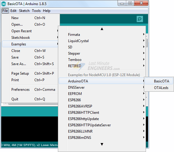
The ESP8266 add-on for the Arduino IDE comes with a OTA library & BasicOTA example. You can access it through File > Examples > ArduinoOTA > BasicOTA.

The following code should load. But, before you head for uploading the sketch, you need to make some changes to make it work for you. You need to modify the following two variables with your network credentials, so that ESP8266 can establish a connection with existing network.

const char* ssid = "..........";
const char* password = "..........";

Once you are done, go ahead and upload the sketch.


#include <ESP8266WiFi.h>
#include <ESP8266mDNS.h>
#include <WiFiUdp.h>
#include <ArduinoOTA.h>

const char* ssid = "..........";
const char* password = "..........";

void setup() {
  Serial.begin(115200);
  Serial.println("Booting NodeMCU");
  WiFi.mode(WIFI_STA);
  WiFi.begin(ssid, password);
  while (WiFi.waitForConnectResult() != WL_CONNECTED) {
    Serial.println("Sorry, Connection Failed! Rebooting NodeMCU...");
    delay(5000);
    ESP.restart();
  }
  ArduinoOTA.onStart([]() {
    String type;
    if (ArduinoOTA.getCommand() == U_FLASH)
      type = "sketch";
    else 
      type = "filesystem";

    Serial.println("Start updating " + type);
  });
  ArduinoOTA.onEnd([]() {
    Serial.println("\nEnd");
  });
  ArduinoOTA.onProgress([](unsigned int progress, unsigned int total) {
    Serial.printf("Progress: %u%%\r", (progress / (total / 100)));
  });
  ArduinoOTA.onError([](ota_error_t error) {
    Serial.printf("Error[%u]: ", error);
    if (error == OTA_AUTH_ERROR) Serial.println("Auth Failed");
    else if (error == OTA_BEGIN_ERROR) Serial.println("Begin Failed");
    else if (error == OTA_CONNECT_ERROR) Serial.println("Connecting Failed");
    else if (error == OTA_RECEIVE_ERROR) Serial.println("Receiving Failed");
    else if (error == OTA_END_ERROR) Serial.println("End Failed");
  });
  ArduinoOTA.begin();
  Serial.println("Ready");
  Serial.print("IP address: ");
  Serial.println(WiFi.localIP());
}

void loop() {
  ArduinoOTA.handle();
}

Now, open the Serial Monitor at a baud rate of 115200. And press the RST button on ESP8266. If everything is OK, it will output the dynamic IP address obtained from your router. Note it down.

Upload New Sketch Over-The-Air

Now, let’s upload a new sketch over-the-air.

Remember! you need to add the code for OTA in every sketch you upload. Otherwise, you’ll loose OTA capability and will not be able to do next uploads over-the-air. So, it’s recommended to modify the above code to include your new code.

As an example we will include a simple Blink sketch in the Basic OTA code. Remember to modify the SSID and password variables with your network credentials.

#include <ESP8266WiFi.h>
#include <ESP8266mDNS.h>
#include <WiFiUdp.h>
#include <ArduinoOTA.h>

const char* ssid = "..........";
const char* password = "..........";

//variabls for blinking an LED with Millis
const int led = D0; // ESP8266 Pin to which onboard LED is connected
unsigned long previousMillis = 0;  // will store last time LED was updated
const long interval = 1000;  // interval at which to blink (milliseconds)
int ledState = LOW;  // ledState used to set the LED
void setup() {
pinMode(led, OUTPUT);
    
  Serial.begin(115200);
  Serial.println("Booting NodeMCU");
  WiFi.mode(WIFI_STA);
  WiFi.begin(ssid, password);
  while (WiFi.waitForConnectResult() != WL_CONNECTED) {
    Serial.println("Connection Failed! Rebooting NodeMCU...");
    delay(5000);
    ESP.restart();
  }
  ArduinoOTA.onStart([]() {
    String type;
    if (ArduinoOTA.getCommand() == U_FLASH)
      type = "sketch";
    else
      type = "filesystem";

    Serial.println("Start updating " + type);
  });
  ArduinoOTA.onEnd([]() {
    Serial.println("\nEnd");
  });
  ArduinoOTA.onProgress([](unsigned int progress, unsigned int total) {
    Serial.printf("Progress: %u%%\r", (progress / (total / 100)));
  });
  ArduinoOTA.onError([](ota_error_t error) {
    Serial.printf("Error[%u]: ", error);
    if (error == OTA_AUTH_ERROR) Serial.println("Auth Failed");
    else if (error == OTA_BEGIN_ERROR) Serial.println("Begin Failed");
    else if (error == OTA_CONNECT_ERROR) Serial.println("Connecting Failed");
    else if (error == OTA_RECEIVE_ERROR) Serial.println("Receiving Failed");
    else if (error == OTA_END_ERROR) Serial.println("End Failed");
  });
  ArduinoOTA.begin();
  Serial.println("Ready");
  Serial.print("IP address: ");
  Serial.println(WiFi.localIP());
}

void loop() {
  ArduinoOTA.handle();

  unsigned long currentMillis = millis();
  if (currentMillis - previousMillis >= interval) {

  previousMillis = currentMillis;
  ledState = not(ledState);
  digitalWrite(led,  ledState);
  }
}

Once you copy above sketch to your Arduino IDE, go to Tools > Port option and you should see something like this: esp8266-xxxxxx at your_esp_ip_address If you can’t find it, you may need to restart your IDE.
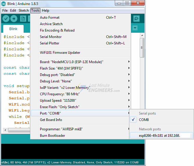
Select the port and click Upload button. Within a few seconds, the new sketch will be uploaded. And you should see the on-board LED blinking.

Smart Switch NodeMCU – Works with Google Home & Amazon Alexa

Google assistant is AI (Artificial Intelligence) based voice command service. Using voice, we can interact with google assistant and it can search on the internet, schedule events, set alarms, control appliances, etc. This service is available on smartphones and Google Home devices.

We can control smart home devices including lights, switches, fans, thermostats and many more devices using our Google Assistant.

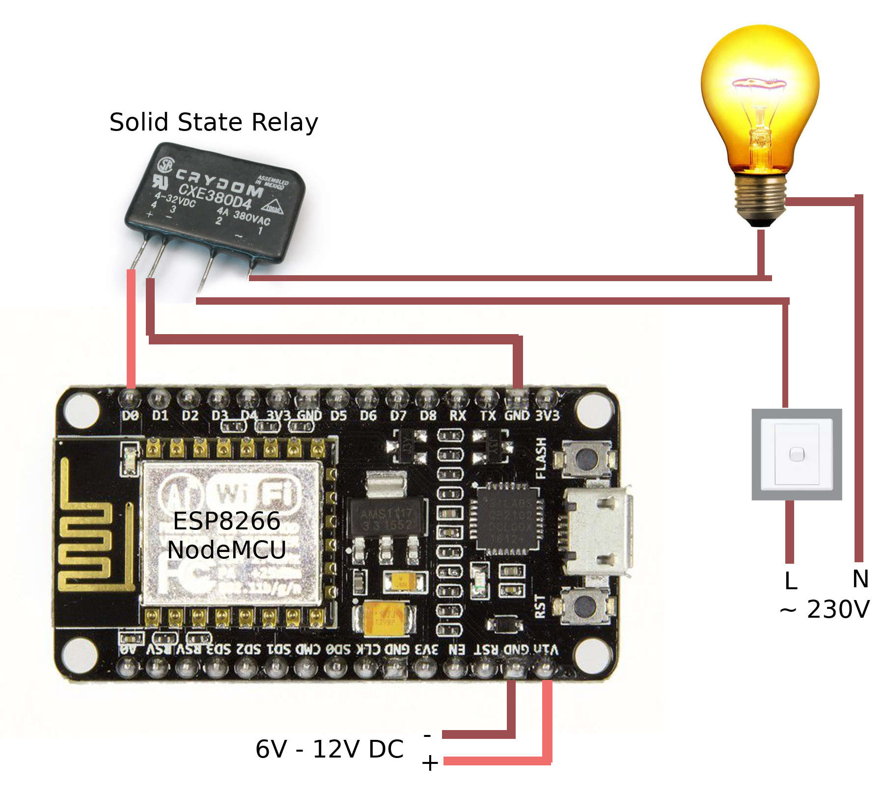
A lot of commercial devices already exist in the market for such application but,. Here i have explained how to build your own smart switch using NodeMCU (ESP8266) development board and few other electrical components.

Components used;

  • NodeMCU (ESP8266) Development Board.
  • Solid State Relay Module.
  • 6V Power Supply Module.
  • Connection Wires.

Above figure explained very simply about the circuit diagram. Be aware when you connecting this to the main power. If you don’t have enough knowledge about connecting this to the main power system, please get some help from a experienced  technician.

Before you connect using above explained diagram, you must programme the NodeMCU development board. Otherwise you cannot control it using Google Smart Home Assistant with voice commands.

In above diagram, i used D0 – Digital pin to control the input signal connected to the Solid State Relay module. When we want to switch on the light, we need to set it to high voltage state (5V), and when we want to switch of the light, we need to set it to low voltage state (0V).

You can find the source code which needs to be uploaded to the NodeMCU development borad using Arduino IDE here. https://github.com/lahirutm/WebserviceLK-IoT/blob/master/arduino_examples/state_save_light_example.ino

Once you programmed your NodeMCU, you must link it with Google Home Assistant to control using voice commands. Please follow the steps explained here.  https://iot.webservice.lk/

Enjoy using your own smart home devices…

Toroidal Transformers

Transformers are made from a pair of solenoids wrapped around a metal core that is usually a ferrite. Toroidal transformers are two coils wrapped around a metal, such as a ferrite or silicon steel, that is doughnut shaped. The coils are either wrapped in different areas or placed one over the other. They are preferred for RF or radio frequency transformers, where they are used to increase or decrease voltages from power sources, and to isolate different parts in a circuit. RF transformers are also used for impedance matching, which means they help connect input and output parts of different circuits.

Here are five other reasons why toroidal transformers are used for many industrial applications:

  1. Low noise and low stray field – The field generated by magnetization, also known as the stray field, is lower in a toroidal transformer, due to the uniform core windings. Less magnetic interference in toroids results in higher performance.

  2. Easy to mount – Using just one screw, toroidal transformers can be easily mounted in a short time. This convenience helps limit maintenance and downtime.

  3. Low operating temperature – Toroidal transformers operate at lower temperatures than transformers with similar specifications.

  4. Light weight core – The core of a toroidal transformer weighs less than typical transformers due to it being comprised of less raw materials.

  5. More economical – Since toroidal transformer cores are manufactured from fewer materials, they weigh less than conventional transformers and use less energy, providing better cost savings and higher return on investment.

The toroidal transformers efficiency makes them useful for a wide array of machines such as audio/visual equipment, security systems, telecommunication systems, industrial control equipment and power distribution equipment. Cost efficiency is an important key to the widespread use of toroidal transformers, as well as the fact that they can be customized for any diameter and height.