A fantastic feature of any WiFi-enabled microcontroller like ESP8266 NodeMCU is the ability to update its firmware wirelessly. This is known as Over-The-Air (OTA) programming.
The OTA programming allows updating/uploading a new program to ESP8266 using Wi-Fi instead of requiring the user to connect the ESP8266 to a computer via USB to perform the update.
OTA functionality is extremely useful in case of no physical access to the ESP module. It helps reduce the amount of time spent for updating each ESP module at the time of maintenance.
One important feature of OTA is that one central location can send an update to multiple ESPs sharing same network.
The only disadvantage is that you have to add an extra code for OTA with every sketch you upload, so that you’re able to use OTA in the next update.
The factory image in ESP8266 doesn’t have an OTA Upgrade capability. So, you need to load the OTA firmware on the ESP8266 through serial interface first.
It’s a mandatory step to initially update the firmware, so that you’re able to do the next updates/uploads over-the-air.
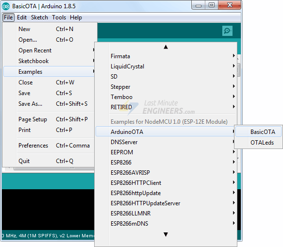
The ESP8266 add-on for the Arduino IDE comes with a OTA library & BasicOTA example. You can access it through File > Examples > ArduinoOTA > BasicOTA.
The following code should load. But, before you head for uploading the sketch, you need to make some changes to make it work for you. You need to modify the following two variables with your network credentials, so that ESP8266 can establish a connection with existing network.
const char* ssid = "..........";
const char* password = "..........";
Once you are done, go ahead and upload the sketch.
#include <ESP8266WiFi.h>
#include <ESP8266mDNS.h>
#include <WiFiUdp.h>
#include <ArduinoOTA.h>

const char* ssid = "..........";
const char* password = "..........";

void setup() {
  Serial.begin(115200);
  Serial.println("Booting NodeMCU");
  WiFi.mode(WIFI_STA);
  WiFi.begin(ssid, password);
  while (WiFi.waitForConnectResult() != WL_CONNECTED) {
    Serial.println("Sorry, Connection Failed! Rebooting NodeMCU...");
    delay(5000);
    ESP.restart();
  }
  ArduinoOTA.onStart([]() {
    String type;
    if (ArduinoOTA.getCommand() == U_FLASH)
      type = "sketch";
    else
      type = "filesystem";

    Serial.println("Start updating " + type);
  });
  ArduinoOTA.onEnd([]() {
    Serial.println("\nEnd");
  });
  ArduinoOTA.onProgress([](unsigned int progress, unsigned int total) {
    Serial.printf("Progress: %u%%\r", (progress / (total / 100)));
  });
  ArduinoOTA.onError([](ota_error_t error) {
    Serial.printf("Error[%u]: ", error);
    if (error == OTA_AUTH_ERROR) Serial.println("Auth Failed");
    else if (error == OTA_BEGIN_ERROR) Serial.println("Begin Failed");
    else if (error == OTA_CONNECT_ERROR) Serial.println("Connecting Failed");
    else if (error == OTA_RECEIVE_ERROR) Serial.println("Receiving Failed");
    else if (error == OTA_END_ERROR) Serial.println("End Failed");
  });
  ArduinoOTA.begin();
  Serial.println("Ready");
  Serial.print("IP address: ");
  Serial.println(WiFi.localIP());
}

void loop() {
  ArduinoOTA.handle();
}
Now, open the Serial Monitor at a baud rate of 115200. And press the RST button on ESP8266. If everything is OK, it will output the dynamic IP address obtained from your router. Note it down.
Upload New Sketch Over-The-Air
Now, let’s upload a new sketch over-the-air.
Remember! you need to add the code for OTA in every sketch you upload. Otherwise, you’ll loose OTA capability and will not be able to do next uploads over-the-air. So, it’s recommended to modify the above code to include your new code.
As an example we will include a simple Blink sketch in the Basic OTA code. Remember to modify the SSID and password variables with your network credentials.
#include <ESP8266WiFi.h>
#include <ESP8266mDNS.h>
#include <WiFiUdp.h>
#include <ArduinoOTA.h>

const char* ssid = "..........";
const char* password = "..........";

//variabls for blinking an LED with Millis
const int led = D0; // ESP8266 Pin to which onboard LED is connected
unsigned long previousMillis = 0;  // will store last time LED was updated
const long interval = 1000;  // interval at which to blink (milliseconds)
int ledState = LOW;  // ledState used to set the LED
void setup() {
pinMode(led, OUTPUT);

  Serial.begin(115200);
  Serial.println("Booting NodeMCU");
  WiFi.mode(WIFI_STA);
  WiFi.begin(ssid, password);
  while (WiFi.waitForConnectResult() != WL_CONNECTED) {
    Serial.println("Connection Failed! Rebooting NodeMCU...");
    delay(5000);
    ESP.restart();
  }
  ArduinoOTA.onStart([]() {
    String type;
    if (ArduinoOTA.getCommand() == U_FLASH)
      type = "sketch";
    else
      type = "filesystem";

    Serial.println("Start updating " + type);
  });
  ArduinoOTA.onEnd([]() {
    Serial.println("\nEnd");
  });
  ArduinoOTA.onProgress([](unsigned int progress, unsigned int total) {
    Serial.printf("Progress: %u%%\r", (progress / (total / 100)));
  });
  ArduinoOTA.onError([](ota_error_t error) {
    Serial.printf("Error[%u]: ", error);
    if (error == OTA_AUTH_ERROR) Serial.println("Auth Failed");
    else if (error == OTA_BEGIN_ERROR) Serial.println("Begin Failed");
    else if (error == OTA_CONNECT_ERROR) Serial.println("Connecting Failed");
    else if (error == OTA_RECEIVE_ERROR) Serial.println("Receiving Failed");
    else if (error == OTA_END_ERROR) Serial.println("End Failed");
  });
  ArduinoOTA.begin();
  Serial.println("Ready");
  Serial.print("IP address: ");
  Serial.println(WiFi.localIP());
}

void loop() {
  ArduinoOTA.handle();

  unsigned long currentMillis = millis();
  if (currentMillis - previousMillis >= interval) {

  previousMillis = currentMillis;
  ledState = not(ledState);
  digitalWrite(led,  ledState);
  }
}
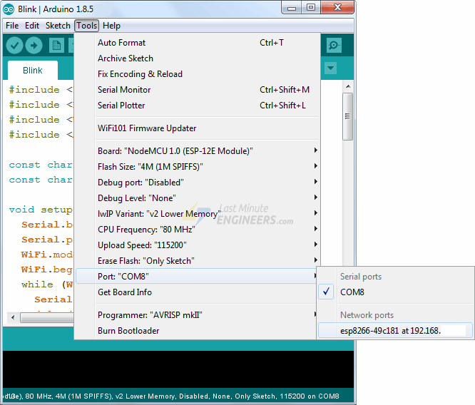
Once you copy above sketch to your Arduino IDE, go to Tools > Port option and you should see something like this: esp8266-xxxxxx at your_esp_ip_address If you can’t find it, you may need to restart your IDE.
Select the port and click Upload button. Within a few seconds, the new sketch will be uploaded. And you should see the on-board LED blinking.